Example of a Process NMR Unit
This analyzer, manufactured by Qualion Ltd, is marketed by Donahue Process Systems Inc.
1. Rack Mounted Computer
The rack-mounted computer provides supervisory control for all other units in the analyzer cabinet. This unit is a PC supplied with standard peripherals and I/O functions, such as an analog-to-digital converter for Channels I and Q, a system control board, control for the sample switching system, and a direct digital synthesizer (DDS). It also provides a communication link to a remote computer or modem link.
2. Switching Control Unit (RF Box)
The Switching Control Unit contains the following major components:
36 MHz crystal oscillator RF Sources Module Lock Transmitter Module
Lock Receiver Module Main Transmitter Module Main Receiver Module 36 MHz RF Filter
3. Shim Control Unit
The Shim control unit converts the digital shim signals from the computer and generates the current for the 50-shim coil pairs. It contains a communication board for coms to the computer, 50 ADC’s and 50 current generators.
4. Power Supply I/O Unit
The Power Supply I/O unit contains digital output modules for sample stop and sample switching valve control, digital input modules for enclosure alarms. A RS-485 Field Point connection for analog outputs and a RS-485 Modbus connection for digital connection to a DCS. It also provides all dc operating voltages for the system.
5. Magnet
The magnet is permanent and built from multiple segments of neodymium- boron-iron. This material is used because its very high field strength-to-mass ratio achieves the desired flux density in a small, compact package. Because the flux must be extremely uniform over the entire air gap, construction of the magnet is complex. The magnet is fabricated from several segments bonded together to form the basic assembly. In addition to the bonded segments of magnetic material, each magnet also contains 50 coils of wire arranged about a Shimming Unit mounted in the center of the magnet between the pole pieces. These coils are used as small electromagnets; the strength and polarity of which can be controlled by varying the current through them so as to improve uniformity of the overall field of the magnet assembly.
Prior to assembly in the manufacturing plant, each magnet segment is “cured” at a high temperature to stabilize its field strength. In the fabrication process, the absolute field strength of each individual segment of the magnet is measured. A computer analysis of this data then determines the best placement of each segment in the final assembly to achieve a consistent, uniform field for the assembled magnet. The segments are then bonded together to form the final magnet assembly. The assembly is placed inside a soft iron cylinder, the ‘envelope’, which constrains the magnetic flux and prevents the magnetic field outside the magnet housing from exceeding a value of as little as 5 gauss. More importantly, the iron cylinder raises field strength in the center of the magnet by pushing the flux toward the center; a process called “condensing the field”. There are electric heater strips and thermistors on the magnet and envelope to heat the assembly to the desired temperature.
6.Probe
The sample probe is mounted inside the permanent magnet in the air gap between the magnet poles. The probe contains two coils; the first, the ‘Main Coil’ is wound around a ceramic or molybdenum tube that is inserted in a hole through the shimming unit in the center of the gap between pole pieces of the magnet. The second coil, the ‘Lock Coil’ is wound on a sealed capsule of lithium chloride beside the main coil in the sample probe inside the permanent magnet. This is provided as a reference standard for setting the frequency of the main transmitter.
The constant magnetic field of the permanent magnet is perpendicular to the axis of the transmitter coil in the sample probe. Since the pulsed ac field introduced by the coil around the sample tube coincides with the vertical axis of the probe, the pulsed magnetic field is therefore perpendicular to the constant magnet field of the permanent magnet.
7. Heater Control Unit
The Magnet Heater Control Unit controls the temperature of the magnet and the envelope. The temperature of the magnet is set at 41°C and the temperature of the envelope is maintained at 37°C. The Heater Control Unit is mounted on the interior wall of the Magnet Enclosure Cabinet and has two PID loops that accept measurement input signals from the thermistors mounted on the magnet itself and the envelope. The outputs of these two PID loops control the currents to electric heater strips.
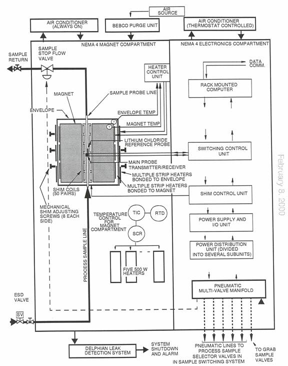
8. Enclosure
The NMR analyzer is housed in a two-door NEMA Type 4 enclosure approximately 48 inches high, 44 inches wide and 30 inches deep. Floor stands are approximately 12 inches high and are welded to the body to make it a freestanding enclosure.
The enclosure with equipment installed weighs approximately 1500 pounds and is equipped with transportation eyebolts. It is fabricated from 304 stainless steel, with all seams continuously welded and ground smooth. A center partition divides the enclosure into Magnet (left) and Electronics (right) compartments.
The magnet side is home to the gas leak detector and the ambient temperature is maintained at 72°F ±1°F. This is accomplished by means of an air conditioner on the outside left wall of the enclosure working in conjunction with a bank of five 500-watt strip heaters and a PID Controller. The ambient temperature in the Electronics side is controlled by an air conditioner on the outside right wall with an internal thermostat set at approximately 70°F.
Principle of Operation
The Qualion Process NMR System
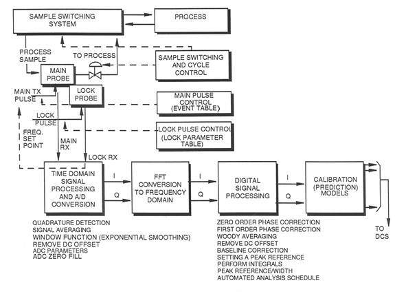
The signal is then digitally processed passed though the prediction models to obtain a prediction, the prediction is then transmitted to a DCS or receiver via analog or modbus outputs. After this has happened the sample stop valve is opened and the cycle is repeated. The lock circuit is constantly performing a NMR experiment on the Lithium Chloride, this is done as a reference. The frequency of Lithium in the NMR magnet is around 22 MHz and therefore does not interfere with observing hydrogen at 60 MHz. Because the magnet is highly dependent on temperature it is impossible to maintain a constant temperature and there for, as we know where the Lithium Chloride peak should be we can reference the main circuit to the same as the Lithium Chloride peak is away from where is should be.
Main Circuit
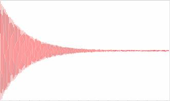
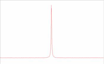
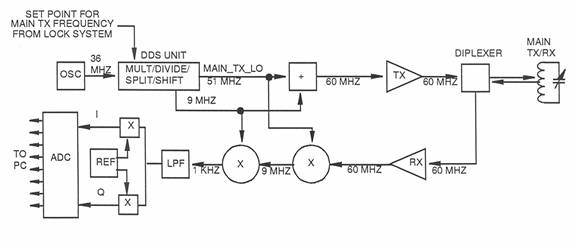
The crystal oscillator outputs a 36 MHz signal, which is sent to the DDS card. The DDS unit multiplies, divides, and/or phase shifts the signal and outputs a 51 MHz signal that is used as the main transmitter and receiver local oscillators (MAIN_TX_LO and MAIN_RX_LO). A 9 MHz signal from the DDS unit is added to the MAIN_TX_LO signal to produce the main transmitter frequency of 60 MHz, which is transmitted to the diplexer and then switched to the main transmitter coil in the probe. After the main transmitter pulse is removed, the nuclei relax and generate a 60 MHz signal in the coil, which flows to the diplexer, where it is automatically switched to the receiver input. The received signal is amplified and then mixed with the MAIN _RX_LO signal (51 MHz) to produce an Intermediate Frequency (IF) of 9 MHz. This signal is then mixed with 9 MHz from the DDS card to produce an audio frequency of approximately 1 kHz. The audio signal is then split into two equal channels, I and Q, phase separated by 90°. The I and Q signals are then input to the ADC, where they are converted to digital form for input to the PC.
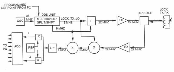
The purpose of the lock system is to provide control of the frequency of the main transmitter pulse, automatically compensating for any minor variations in magnet field strength and temperature. The lock system continuously detects the resonant frequency of the nuclei in a known sample fluid, lithium chloride, and then sets the frequency of the main transmitter to be a fixed ratio to this reference. Since the reference fluid capsule is located inside the main probe, it is subjected to the same magnetic field and temperature as the main transmitter/receiver. Therefore, a change in one affects the other. The lock system functions in the same general way as the main transmitter system, except that the basic transmitter frequency is approximately 22 MHz, the resonance frequency of lithium in a magnetic field of 1.5 tesla. The frequency of the lock transmitter is swept over a range of about 1 MHz (22-23 MHz) as it searches for the resonance frequency of lithium. When it first detects a resonant response (significant increase in signal level) as it increases frequency during the search, it stores this value and then jumps to a higher frequency and approaches resonance from the other direction. When it detects a resonance response as it approaches from the other direction, it stores this frequency and then jumps to a frequency at the mid point between the two stored values and then “locks” on this frequency as the resonance frequency of lithium. The output of the lock system is used as the set point of the main transmitter circuit, which maintains the main transmitter frequency in a fixed ratio to this “lock” frequency.
To obtain a rough magnetic field, the field homogeneity of the permanent magnet is adjusted by mechanical alignment of the magnet pole faces. The more parallel the pole faces, the more homogeneous the magnetic field. The first step in the process of adjusting magnetic homogeneity is to adjust the position of the magnet's pole faces by turning adjustment bolts which hold the pole faces in position. Adjusting these bolts tilts the pole faces relative to each other with the aim of making the pole faces more parallel. In old electromagnetic magnets, if the bolts ran out of range, thin pieces of brass were placed between the magnet yoke and the pole pieces to move the pole pieces as parallel as possible. These thin pieces of brass were also placed in other strategic locations to make the pole faces parallel in a manner not addressed by the adjustment bolts. The metal pieces were called shim stock and the seemingly endless process of placing and removing pieces of shim stock acquired the name "shimming". This is, however, a simple mechanical adjustment that only gets the NMR to a symmetric half height of 700 Hz. To increase performance, reduce the difficulty of adjusting magnetic homogeneity, and reduce the manufacturing difficulty of the magnets, an electronic "shimming" process is used, which uses a series of small electromagnets (essentially shaped coils) having very specific magnetic field contours. These small coils are placed around the sample area in different orientations. Each small coil can be used to adjust the shape of the magnetic field gradients by simply passing different currents through the coil. A complete series of these coils can be used to adjust the magnetic field homogeneity to a given level of “purity”. The process of adjusting the magnetic field homogeneity by adjusting the current in each of the coils has retained the name “shimming” and the small coils assumed the name "shims".
Systems are marketed through Donahue Process Systems Inc
Contact John Edwards for details and visit the Process NMR Associates web page for application examples.